Essetre Techno PM Sips

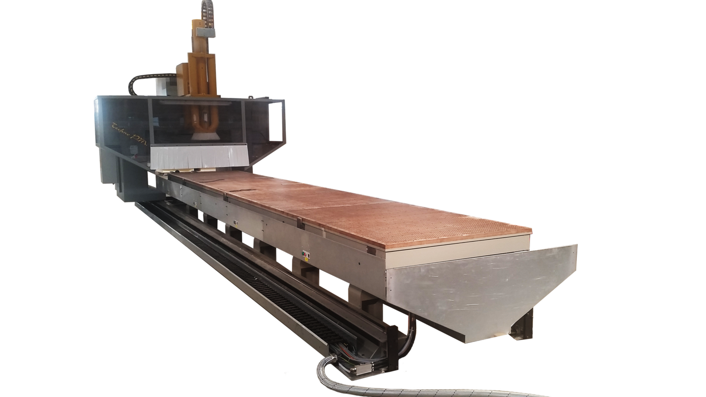
About the EssetreTechno PM Sips

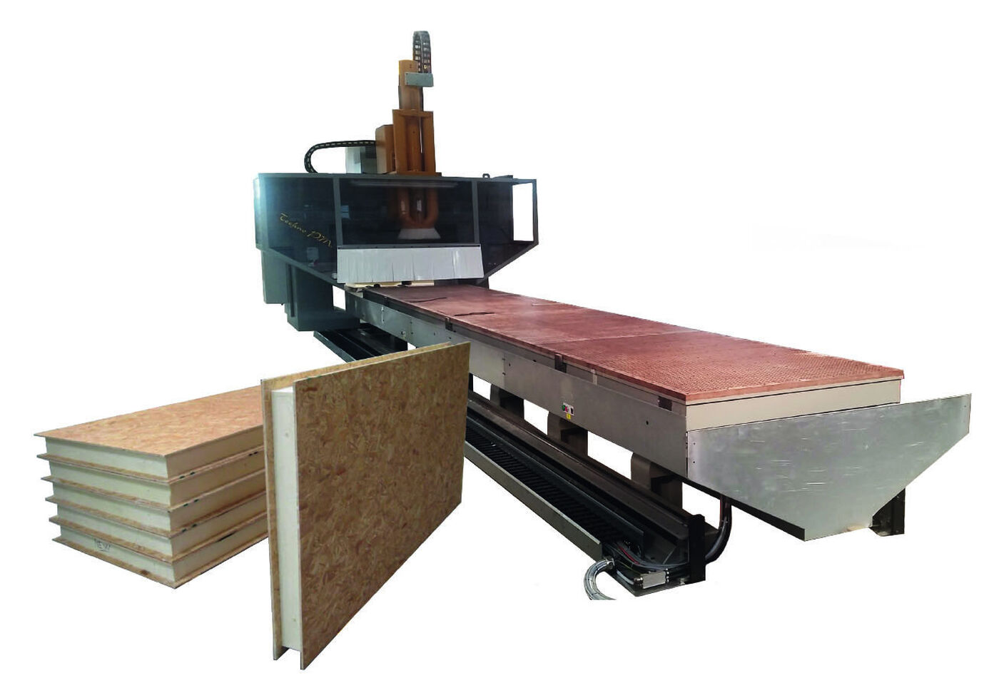
For modern house and buildings manufacturers, this specifically designed Techno Pm Sips machine from Essetre is the ideal solution for processing sips panels with minimum handling. It is a working centre with 3/4 or 5 interpolating axes for processing of SIPS panels, with moving portal frame in Y and manual infeeding/outfeeding direction to be defined.

Essetre Techno PM Sips Features

Tick bullet point THE STRUCTURE Consisting of a high resistance and stability moving carpentry portal frame. AXIS MOTORS X-Y-Z axis movement by means of brushless motors operated by inverter, maintenance free.
Tick bullet point AXIS MOVEMENT The movement of the X, Y and Z-axes is by means of pinion on a hardened rack with grinded inclined teeth.
Tick bullet point SLIDING GUIDES Sliding guides with preloaded recirculating roller slides with a very low friction coefficient and a very high precision, automatically lubricated.
Tick bullet point ELECTROSPINDLES Electrospindles designed and manufactured by us. High power, tool connection by means of cylindrical collet, pneumatic clamping for the automatic tool-change. Our electrospindles are life lubricated.
Tick bullet point PLANT ENGINEERING ELECTRIC PLANT According to the CE norms with equipment installed in airtight cabinet complete with electro fan (or conditioner) for air recirculation inside the cabinet itself and consequent cooling of the equipment contained in it. All electric, electronic, pneumatic and electro-pneumatic components are first-choice products supplied by Companies having an international importance, so that the spare parts can be easily found on the various markets.
Tick bullet point HIGH FREQUENCY INSTALLATION High frequency system realized for the use of the inverter with spindle revolutions programmable from 1000 to 18000 rpm by means of the NC. The inverter, electronic frequency converter, has been studied, designed and manufactured in cooperation with a company specialized in electronic equipment for our electrospindles in order to assure the optimum usage of the power of the heads according to the diameter of tools used, to the peripheral speed of these latter, to the sharpening state, to the axis feed speed and to the power torque in relation to the required rpm.
Tick bullet point LUBRICATION SYSTEM OF THE SLIDING GUIDES Grease centralized lubrication system for the automatic lubrication of the sliding guides by means of electropump controlled by the NC. When the lubricant reaches the minimum level in the tank, an alarm signal is generated and displayed on the screen.
Tick bullet point LUBRICATION SYSTEM OF THE PNEUMATIC DEVICES Through fog nozzle filter group for electrovalves, pneumatic cylinders and any other foreseen pneumatic device.
Tick bullet point CONDITIONING GROUP: to keep the electric cabinet and the equipment contained in it at the optimum and constant temperature.
Tick bullet point ELECTROSPINDLE’S COOLING SYSTEM: Liquid cooling to keep its casing at the optimum temperature.
Tick bullet point NUMERICAL CONTROL Our machine is equipped with numeric control NUM made by Schneider Group. The typology and the model to be installed are decided according to the processing requirements and the machine type.
Tick bullet point MACHINE EQUIPMENT No.1 Moving portal frame on Y axis on which the following components are installed: No.1 Milling unit 3,4 or 5 Axis provided with: Electrospindle of 12 kW at 7000 rpm Rpm programming from 1000 to 18000 Tool connection type HSK 63F Liquid cooling X-axis stroke 1400 mm Z-axis stroke 1350 mm Tool-holding magazine for tool-holders type HSK 63F available, position and number of tools available according to the machine configuration. No.1 Inverter of 22 kW to program the spindle’s rpm from 1000 to 18000. No.2 Tracks installed on a high resistance and stability carpentry structure with two linear recirculating roller guides on which the moving portal frame slides. No.1 Safety cabinet with metal structure and shock-resistant polycarbonate walls on the portal frame to reduce chips, dust and noise coming out. The cabinet is provided with air nozzles on the two sides to avoid accumulation of dust inside the cabin and help the collection in the collecting tank and conveyor. No.1 Electric cabinet integral with the moving portal frame containing the electric and electronic devices. No. 1 Rexilon worktable with customizable length: included dry vacuum pump of 250 cm/h for holding the workpieces during the processing. Series of automatic references on the front of the table and on the side. No. 1 Vacuum plant composed by indipendent areas (the number it depends on the total lenght of the machine) managed automatically during the cycle by the CN or manually by the operator as needed. No. 1 Conveyor belt under the basement of the machine to collect all the chips and dust from the cabin and collecting tank and bring it outside the machine. No. 1 Predisposition on the machine for the installation and management of the second working area with one more worktable for the non stop cycle. No. 1 Conditioning group to keep the electric cabinet and the equipment contained in it at the optimum and constant temperature. No. 1 Elecrospindle liquid cooling to keep its casing at the optimum temperature. No. 1 Grease centralized lubrication system for the automatic lubrication of the sliding guides by means of electropump controlled by the NC. When the lubricant reaches the minimum level in the tank, an alarm signal is generated and displayed on the screen. No. 1 Lubrication system of the pneumatic devices through fog nozzle filter group for electrovalves, pneumatic cylinders and any other foreseen pneumatic device. No.1 Mobile control console containing 15” TFT colour monitor, keyboard, push-buttons, warning lights, CNC and PC. No.1 Remote handset control unit for the manual control of the axes, START, STOP and RESET of the program. No.1 Numerical control model “NUM” SERSIES 1000.
Tick bullet point SOFTWARE No.1 Graphic software Essetre Walls or equivalent as required No.1 Software RTCP: The RTCP (Rotation around Tool Centre Point) has been designed to compensate automatically for the offsets caused by moving the rotating axes of a 5-axis machine. This compensation is achieved by moving the main machine axes. It preserves the position of the tool centre.

Product Documentation

Essetre Techno PM Sips Specification

Controlled axis No. 3/4 or 5 controlled Axes X–Y–Z-B-C
X-axis stroke mm 1400
Y-axis stroke mm length variable to be confirmed to suit customer.
Z-axis stroke mm 1350
X-axis speed m/min 70
Y-axis speed m/min 70
Z-axis speed m/min 32
Electric installation Volts 400/50Hz ± 5%
Air consumption (7 bar) Nl/min 100