


Select and purchase Altendorf spares parts from R&J Machinery. We are the home of Altendorf UK, and offer the widest range at the best prices.
Used Biesse Skipper V31
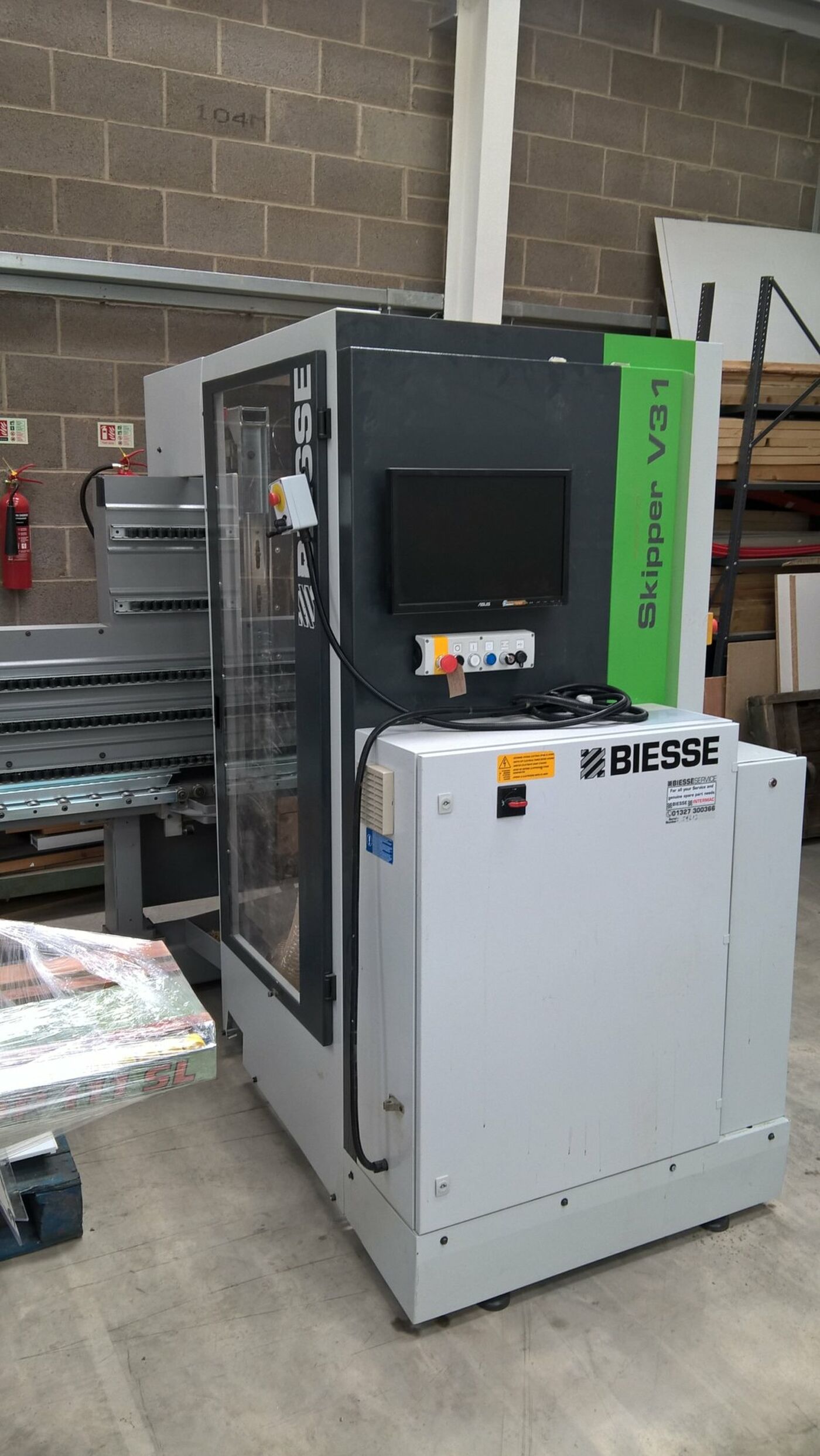
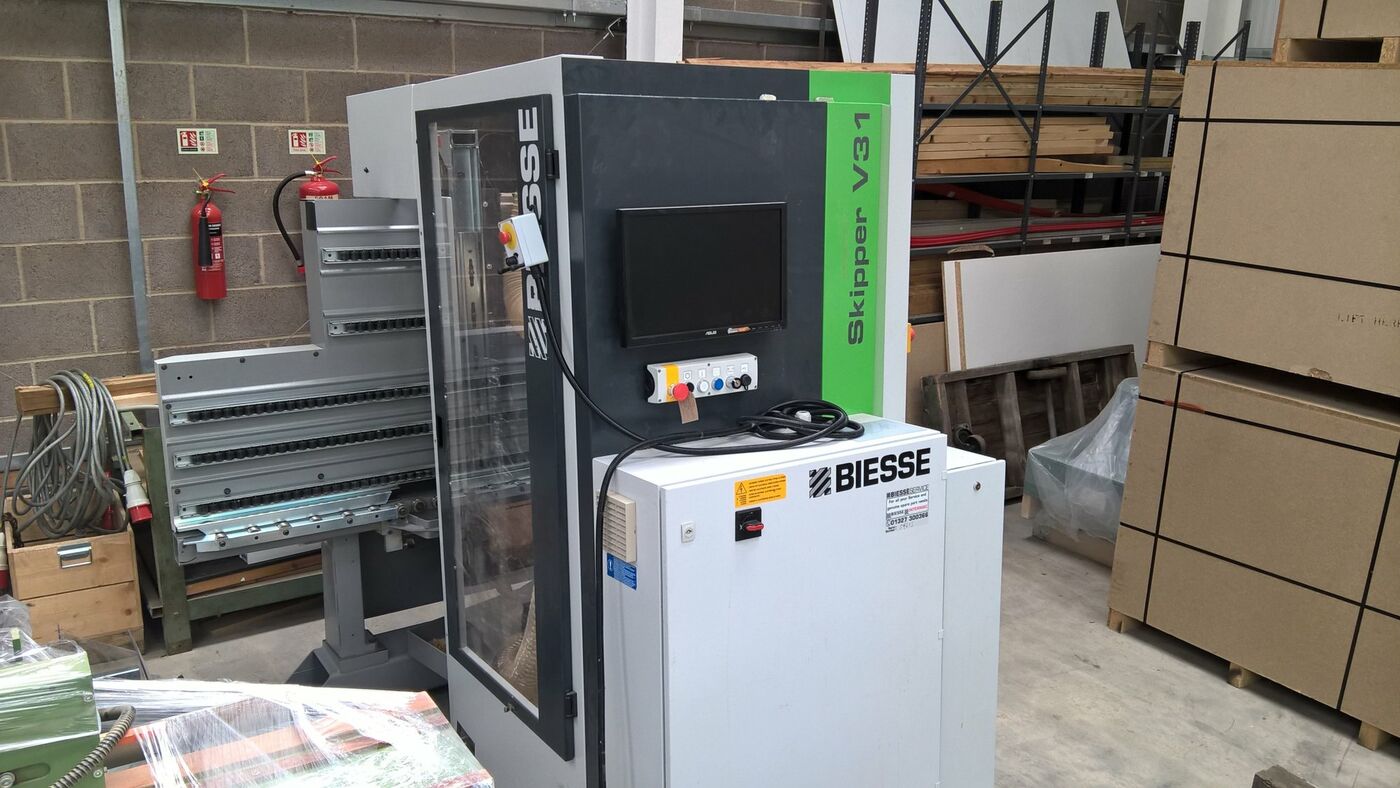
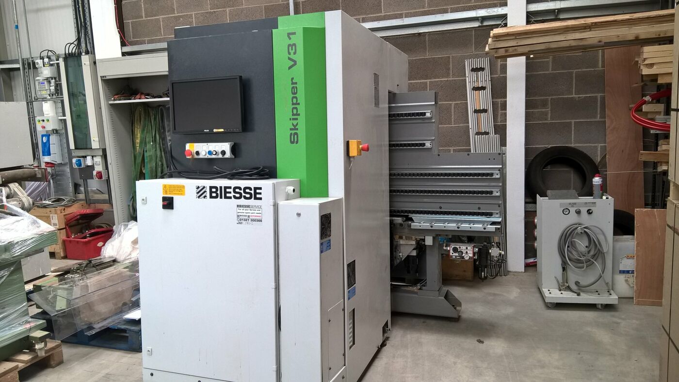
About this used Biesse Skipper V31
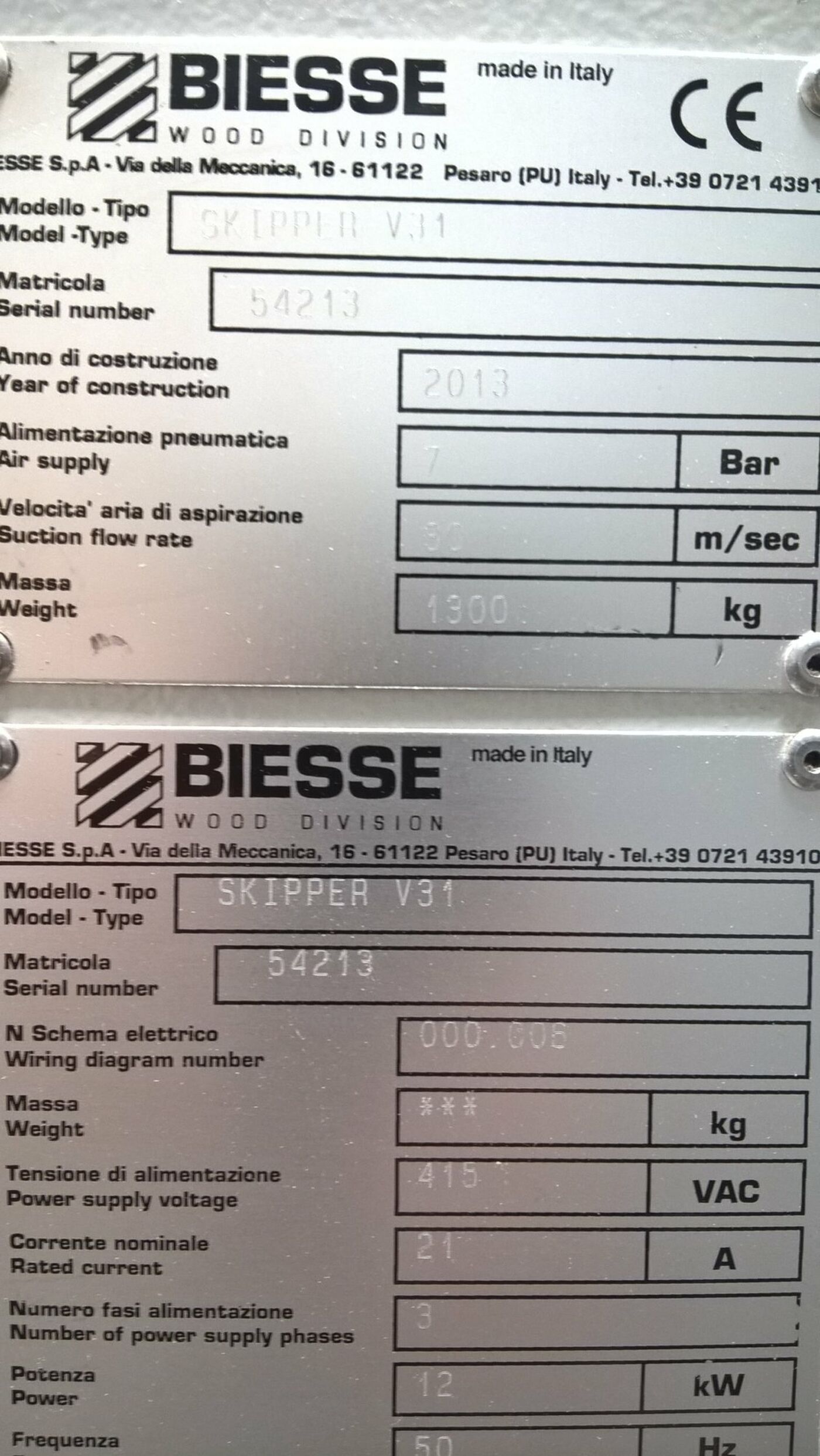
A great chance to purchase a Biesse Skipper V31, year 2013, having done little work.
PANEL MACHINING CENTRE SKIPPER V31
CNC panel machining centre - ‘X’ working field 2500 mm, ‘Y’ working field 900 mm.
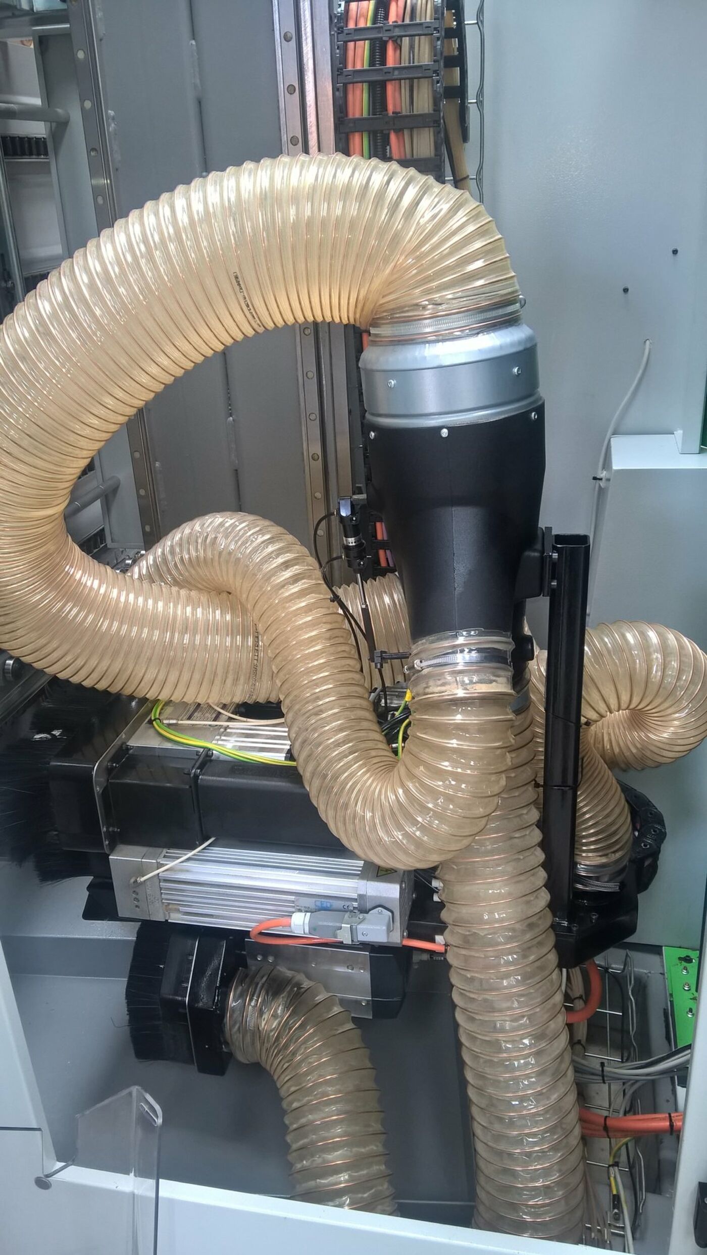
The machine is equipped with 10 vertical independent spindles, 6 horizontal independent spindles and a unit equipped with grooving saw - dia. 120 mm - in ‘X’ direction (BH17), and a Router.
Used Biesse Skipper V31 Features
Used Biesse Skipper V31 Specification
| Panel Lengths | Length - X 200 - 2.500 mm |
|---|---|
| Panel Widths | Width - Y 70 - 900 mm |
| Panel thickness | Thickness - Z 10 - 70 mm |
| WORKING FIELDS OF THE TOOLS | (the dimensions - min. max. - refer to tool axis) |
| Length (X) | Drilling 0 - 2.500 (*) mm |
| Length (X) | Routing (with electrospindle) 0 - 2.500 (^) mm |
| Length (X) | Grooves (with sawblade) in X direction 0 - 2.500 (^) mm |
| Width (Y) | Drilling 0 - 900 mm |
| Width (Y) | Routing (with electrospindle) 0 - 920 mm |
| Width (Y) | Grooves (with sawblade) in X direction 40 - 900 mm |
| Thickness (Z) | Horizontal holes 5 - 35 (°) mm |
| NB | (*) 3.200 mm as option |
| NB | (^) With gripper repositioning |
| NB | (°) The max. dimension may reduce depending on the panel side being machined and on the gripper positioning. |
| NB | The data depend on the tool characteristics / panel thickness. |
| BH17 OPERATING UNIT | • No. 10 vertical independent spindles positioned at 32 mm centerdistance, designed with grub-screw spindle coupling, of which: |
| BH17 OPERATING UNIT | no. 5 spindles aligned in ‘X’ direction - “System 32”, |
| BH17 OPERATING UNIT | no. 5 spindles aligned in ‘Y’ direction; |
| BH17 OPERATING UNIT | No. 6 horizontal independent spindles positioned in X and Y directions, designed with grub-screw spindle coupling, of which: |
| BH17 OPERATING UNIT | no. 4 spindles positioned in ‘X’ direction (no. 2 units with double outlet), |
| BH17 OPERATING UNIT | no. 2 spindles positioned in ‘Y’ direction (no. 1 unit with double outlet); |
| BH17 OPERATING UNIT | No. 1 Grooving Saw Unit diameter 120 mm, RH rotation - Fixed working direction in 'X' |
| Saw diameter mm 120; max. | working depth 25 mm; |
| Saw cutting thickness | 4 mm |
| RH tool rotation; | tool fastening through screws; |
| Power delivered at 18.000 rpm in S1 duty: | 4.5 kW (6 HP); linear power increase |
| Rotation speed from 6.000 up to 18.000 rpm, | programmable by NC |
| Max. tool diameter | 20 mm |
| BIESSEWORKS - | Advanced programming system |
| 3D simulation of the tool path | Yes |
| Approximate calculation of machining time | Yes |
| Automatic pocketing of any shape with the possibility of leaving islands in relief at different dept | Yes |