


Select and purchase Altendorf spares parts from R&J Machinery. We are the home of Altendorf UK, and offer the widest range at the best prices.
Used Weeke Venture 3
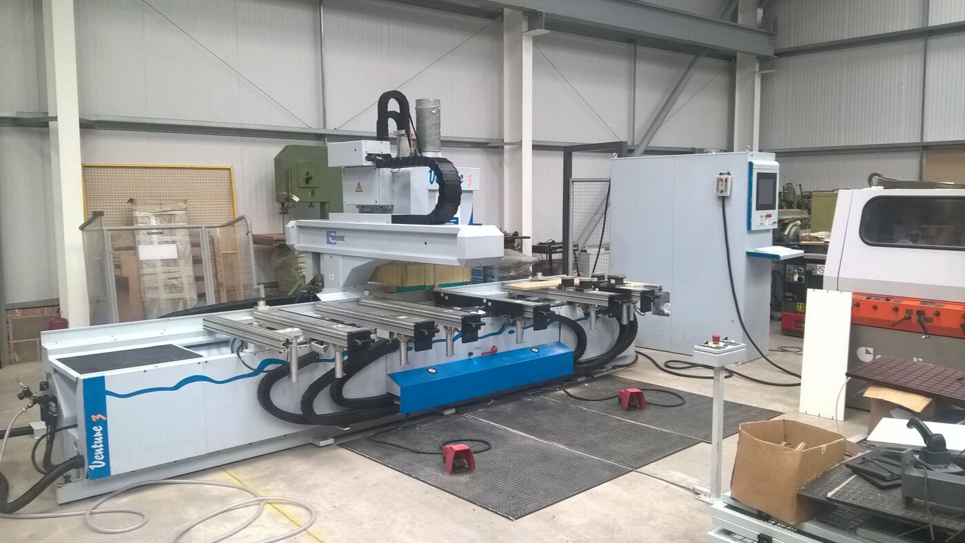
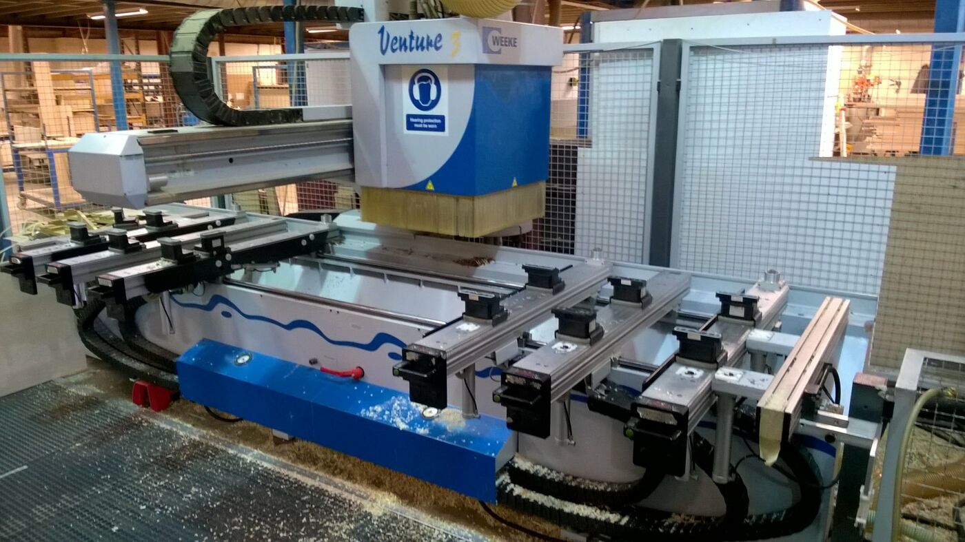
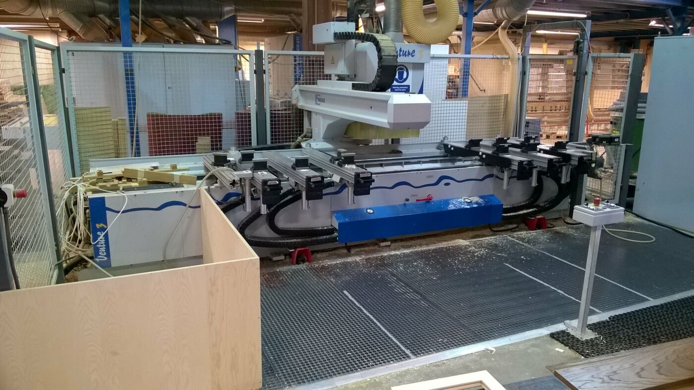
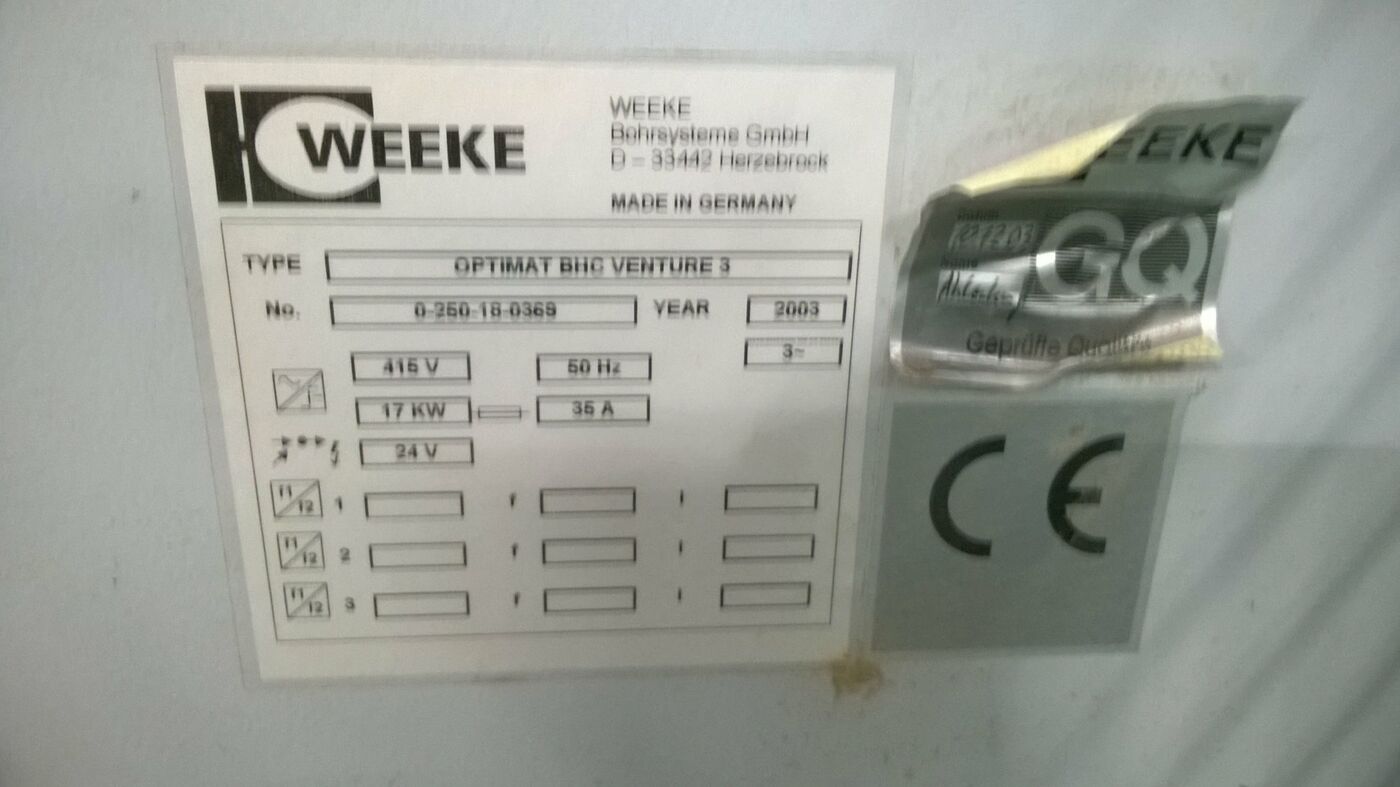
Weeke Venture 3 in very good condition with 4th Axis from year 2003, machine has been very well looked after, and is only available due to the previous owners upgrade to a 5 axis Machine.
Machine has main Router, Vertical and Horizontal drills and saw. The machine is now in stock at R&J Machinery.
Please contact our sales team for more information or to view the machine.
BASIC MACHINE
- Basic machine frame and carriage in solid ribbed steel construction
- Carriage movable in X-direction
- Cross support movable in Y- and Z-direction
- Paint grey RDS 240 80 05
- Central extraction of the processing unit and separate dust connection for the dust extraction device
GUIDING SYSTEM AND DRIVE TECHNIQUE
- Axis adjustment (X-/Y-/Z-direction) via a compact linear guiding system, dust protected Rack gear in X-direction and ball bearing spindle in Y- and Z-direction
Travel range of the axes:
X = 3810 mm
Y = 1735 mm
Z = 220 mm
- Digital drive technique in X-Y- and
Z- direction. (Sercos)
Axis speeds:
X = 100 m/min
Y = 50 m/min
Z = 20 m/min
Consisting of:
- maintanance free AC servomotors with high resolution optical encoder and high system precision.
- digital drive control with higher reliability and faster cycle times (2 ms)
- digital control via lightwave conductor bus-system (SERCOSRING)
3. CONSOLE TABLE WITH LED- DISPLAY
Tubeless vacuum clamping system for clamping of coated and uncoated plate materials.
The positions of the workpiece consoles which are programmed in WoodWop can be displayed at the consoles by LED-display.
The individual positions are adjusted by measuring scales and indicators.
The workpieces consoles are guided on a dust protected, hardened and ground guiding system. For adjusting the workpiece consoles are unclamped pneumatically.
The vacuum cups are clamped by means of a vacuum.
Working field:
X = 3250 mm (Length)
Y = 1220 mm (Width)
Z = 125 mm (Thickness)
The max. workpiece thickness which can be processed depends on the length of the tool
Consisting of:
6 workpiece consoles which can be infinitely adjusted in X-direction, suitable for the tubeless positionable vacuum cups
6 LED displays for optical control of the console and vacuum cup positions.
6 measuring scales in X-direction (1 per console)
1 measuring scale in X-direction
Stop cylinders to position the workpieces to be processed. All stops are lowerable via program.
4 rear stops for workpieces with a width of more than 960 mm
6 front stops for narrow workpieces with a width of more than 960 mm
2 stops for lateral positioning of the workpieces in width for the right hand working field (manually adjustable)
2 stops for lateral positioning of the workpieces in width for the left hand working field (manually adjustable)
6 tilting stops which can be fitted manually, for surface material overhang
Note: for the front stop row
4 controlled workpiece feeding rails (synthetic material) for easy positioning of heavy workpieces. (fitted to the consoles 1, 3, 4 and 6)
1 vacuum connection for connection of selfmade templates to the right hand working field
1 liquid cooled low-maintenance vacuum pump with a capacity of 100 m/min.
1 Laser pin
Via a separate NC-program the exact vacuum cup positions are shown via a laser beam (cross hairs).
The laser is fitted to the processing support of the machine. The positions which were adjusted via LED display and scales can be controlled additionally in rapid traverse
During this operation the operator is not permitted to enter the safety area of the safety mats.
Router contour control:
The laser control for the router contour can be programmed in WoodWOP. The cross hair laser can therefor carry out the control of the vertical router contour (center point lane).
The complete contour is not displayed graphically instead the router contour is simulated.
Hand terminal
- With potentiometer and emergency stop switch to control the machine (e.g. for running of complex processing programs)
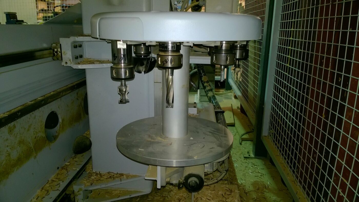
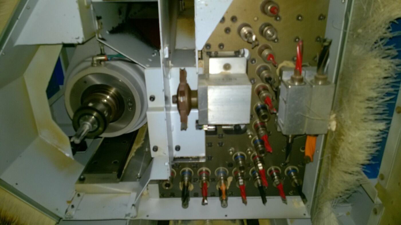
5. PROCESSING CONFIGURATIONS
V19,H4X/2Y,G1,F1-HSK-9KW,C-Axis,TC8 rear
V19 HIGH SPEED 7500 incl. quick change and spindle clamping.
Vertical drilling aggregate with manual quick changing system and steplessly programmable High Speed range.
Furthermore the vertical individually selectable spindles are equipped with forced spindle clamping to ensure the required drilling depth.
Working capacity: refer to separate layout
Pre-stroke
Z-direction: 60 mm
Drilling depth: max. 38 mm (up to 55 mm but witha special drill)
Rotation: right/left
RPM: 1500 - 7500 1/min, frequency controlled
Drive: 2,7 kW
Shaft diameter: d = 10 mm
Total drill length: 70 mm
Drill diameter: max. 35 mm
Spindle distance: 32 mm
Spindle type: individually selectable
Arrangement: 9 spindles X-direction (row holes)
8 spindles Y-direction (construction)
2 separate spindles.
H4X/2Y
Horizontal boring block with 4 spindles in X-direction which can be activated separately.
Two spindles each (pitch 32 mm) arranged right and left hand in X-direction.
Working capacity: refer to separate layout
Drilling depth: max. 38 mm
Drilling height in Z-direction: 38 mm from upper workpiece edge
Direction of rotation: right hand / left hand RPM: 1500 - 7500 1/min frequency-controlled
Shaft diameter: 10 mm
Total length of drill: 70 mm
Drill diameter: max. 20 mm
Type of spindle: individually selectable
Horizontal drill block with 2 individually
selectable spindles via program.
1 spindle each arranged at the front and rear in Y-direction.
Working capacity: refer to separate layout
Drilling depth: max. 38 mm
Drilling height in Z-direction: 38 mm from upper workpiece edge
Direction of rotation: left RPM: 1500 to 7500 1/min frequency-controlled
Shaft diameter: 10 mm
Total length of drill: 70 mm
Drill diameter: max. 20 mm
Type of spindle: individually selectable
GS1
Grooving saw in X-direction
Working capacity: refer to separate layout
Cutting depth: 10 mm
Cutting section: max. 50 mm2
Direction of rotation: right hand
Speed: 2000 to 6500 1/min frequency-controlled
Saw blade
inner bore: 30 mm
Tool diameter: 100 mm
Saw blade thickness: max. 5 mm
R1-HSK63-9 KW
Tool change routing spindle incl. liquid cooling system for the use of shaft tools which are automatically changed from a plate changing magazine.
Working capacity: refer to separate layout Tool holder: HSK cone
Tool changing automatic
Direction
of rotation: right hand / left hand Speed: stepless 1250 - 24000
1/min programmable
Drive: frequency controlled
AC-motor
Max. capacity at the tool: up to 7,5/9 kW in continuous and intermittent operation (S1/S6 - 50%)
Spindle
lubrication: permanently lubricated
Cooling: liquid cooling system
Bearing: hybrid bearing(ceramic) less friction, higher stiffness and max. operating life C-AXIS AGGREGATE INTERFACE To take the adapter aggregates. Incl. interface pneumatics and rotatable drive
(stepless C-axis with torque a. 3-pointsupport)
C-Axis range: 360 degrees
Torque: for 3 point-support
Gear: slanted toothed gear pinion
TC8 REAR
Automatic tool change magazine for 8 places (plate changer),set up in X-direction moving with the support.The change plate magazine is designed for the use of routing tools with HSK cone.
Arrangement: in X-direction moving along with the support
Magazine places: 8 tool places
Due to varying construction of different routers the numbers of tools which can be placed into the magazine can vary as well.
Tool weight: max. 5 kg incl. HSK holder
Tool diameter: max. 100 mm when equipping with 8 router tools
Possible tool diameter: max. 100 mm when fully equipped(8 router tools) max. 160 mm when using tools with small diameters or with empty places besides Adapteraggregates: max. 4 can be equipped
Tool change time: approx 12 - 18 sec. chip to chip
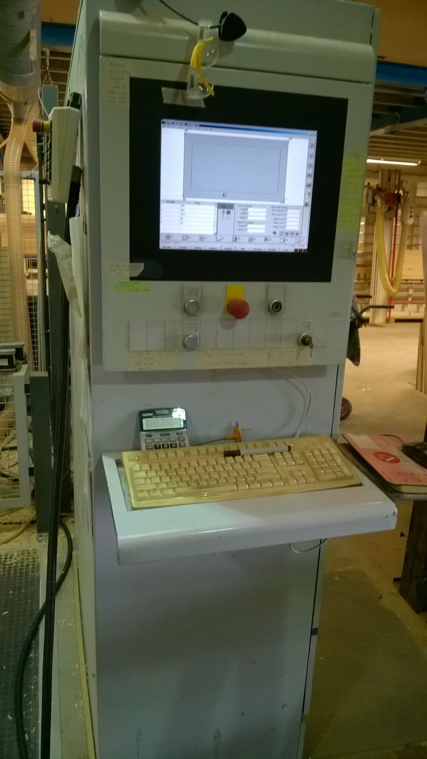
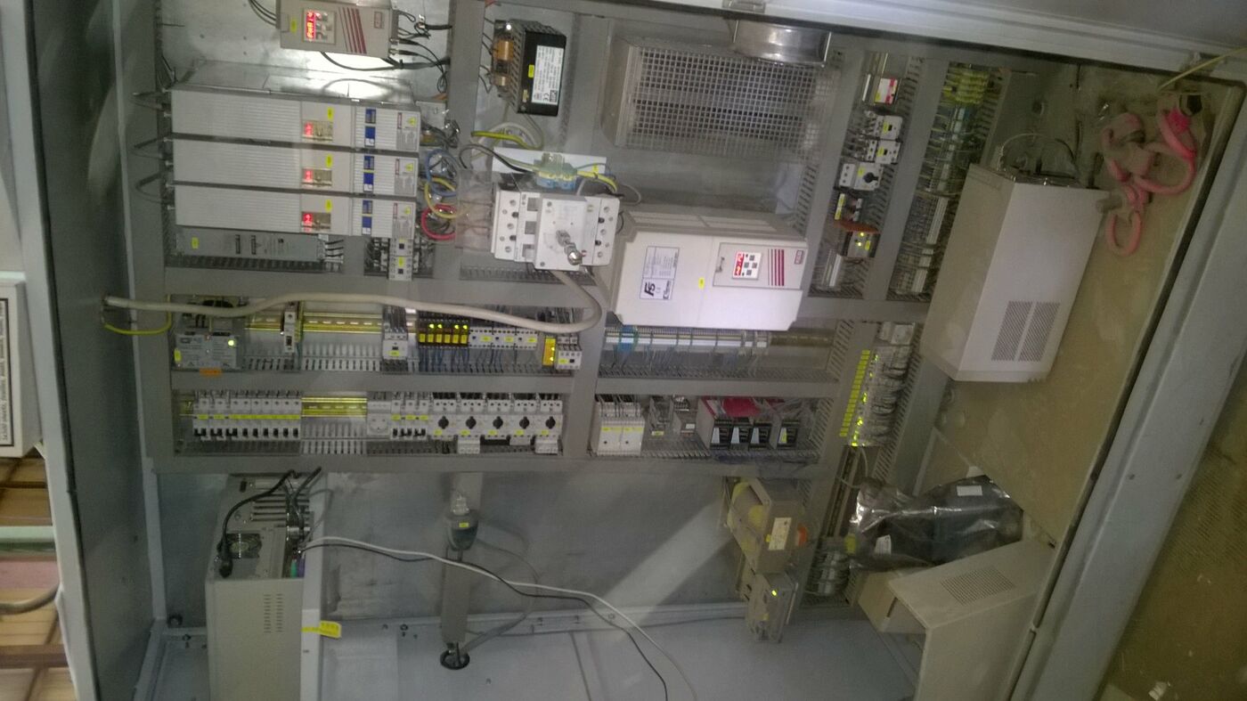
6. CNC Control and Software
The electrical switch cabinet with
integrated operating board is positioned
freely at the right hand machine side.
6.1 HARDWARE: POWERCONTROL SYSTEM
- CNC-Control incl. drive modules
- Intelligent control system, while the
CNC-Control steers the processes new data
can be independantly inserted at the PC
- PC (Personal Computer) for operator guiding
- Intel Pentium 4
- English operating system Windows XP embedded
- 15 inch TFT graphic monitor
- min. 256 MByte RAM
- min. 40 GByte HDD
(diverse partitions)
- 3 1/2 inc diskette drive
- Free port (EtherNet) is optionally onboard
Addtionaly PCI ports allow further
network cards
- Seriel interface for barcode, modem
oder ceiling laser
- Parallel interface for printer
- CD-ROM-drive for reading and writing of
CD`s (no dust protection guaranty)
6.2 SOFTWARE: POWERCONTROL SYSTEM
- WOODWOP
WOODWOP is a workshop orientated programming
system (WOP), which has been designed
especially according to the requirements of
a stationary technology in industry and
craft. Operator guiding for easy programming
processing programs. Due to a standardized
data format processing programs can be
interchanged between different machines
of the Homag group.
MACHINE DATA RECORDING (MDR)
The machine and service data record memorize
the number of workpieces, operation times,
idle times, breakdown times and production
times. When a pre-determined limit is
displayed an automatic maintenance request
is given.
PRODUCTION LIST
Within the production list the production
steps can be organized and recorded.
The lists are processed line by line or
on all places at the same time. Up to 10
variables for the use of variant programming
can be defined.
NC-SIMULATION AND TIME CALCULATION
A ''moving'' aggregate layout simulates the
processing steps in the determined order of
the NC-program.
Further parameters are possible:
- Time calculation approx. +/- 10%
- Positioning area
- Collision check
- Checking of the vacuum cup position
Simulates all 3-axis processings.Delivered
with copy protection (dongle).
7. SOFTWARE FOR EXTERNAL PC
- 3D WOOD DESIGN PACKAGE
The Wood Design Package is a modern 3D
construction program for the interactive
creation of carcase furniture and interior
elements.
- WOODWOP FOR PC
With this programming software processing
programs can be created on a PC externally,
e.g. in the engineering department.
8. PROVISION TELESERVICE, MODEM
Comprises the general provision of teleservice
capability of the machine incl.modem
and use of teleservice features within the
guarantee period. After the guarantee period
a corresponding teleservice contract must be
signed in order to use the teleservice.
9. CE-SECURTIY- AND SAFETY UNITS.
- Safety fences in the lateral and rear
areas.
- The saftey mats divided in 3 areas in front
of the machine for two-field operation.
While the machine operator sets up one work
field side the processing center can carry
out the processing on the opposite side.
10.USV INCLUDING VOLTAGE STABLIZER
Supplies the electronics as well as the
regulating circuit with electricity for
appr.3 minutes via the integrated batteries.
The interruption-free power supply also
serves as a voltage stabilzer for the
electronics as in case of overvoltage resp.
undervoltage the batteries are also in
operation.
11.WEEKE QUALITY PACKAGE
- The energy supply cable (cable tow)
in X-Y and Z-direction are supplied in
sealed execution.
- The energy supply cable incl. pneumatics
(cable tow for the workpiece supports) is
supplied in sealed execution.
- The linear guides in X-and Y-direction
are delivered with a protection cover(metal)
12 TOOLING START-UP KIT
- DRILLING
1 pc. cylinder head drill Z2+V2HM d = 15 mm
(30300-5-15070-L)
1 pc. cylinder head drill Z2+V2HM d = 35 mm
(30300-5-15070-R)
4 pcs. dowel hole drills HM d = 5 mm
(30540-5-05035-R)
5 pcs. dowel hole drills HM d = 5 mm
(30540-5-05035-L)
7 pcs. dowel hole drills HM d = 8 mm
(30540-5-08035-R)
7 pcs. dowel hole drills HM d = 8 mm
(30540-5-08035 L)
HSK- TOOL HOLDER
2 HSK tool holders
(1 x short version Sales No. 9501)
(1 x long version Sales No. 9502)
1 collet d=25mm
1 collet d=10mm
GROOVING SAW BLADE
Diameter 100 mm
1 flat tooth grooving d = 100 mm/W= 3,2 mm
d = 30 mm Z = 20
13. DOCUMENTATION
- Documentation in printed form and as
CD-ROM incl. spare-parts catalog and switch
plan
Number : 1603 1 x left
HSK63 DRILLING/ROUTING/SAWING, 2 SPINDLES
Drilling depth: max. approx. 50 mm
Tool holder: for collet ER 25
Tool diameter: max. 20 mm
Cutting depth: max. approx. 50 mm
Router receptacle: for collet ER 25
Saw blade diameter: 150 mm to 180 mm
Sawing depth: max. 40 mm
Saw blade thickness: max. 8 mm
Saw blade holder: 30 mm receptacle
drilling, 4 side drills
5,5 mm diameter,
partial circle 52 mm
diameter
Rotation: max. 15000 1/min
programmable
Indexing angle: 360 degrees
Aggregate holder: HSK F63 cone
Tools and collets are not included!
Note: The saw blade has to be unclamped during
boring or routing. For a saw blade diam.
of more than 150 mm the unit is automatically
placed into the tool changing
magazine.
For the BHC 2xx and 3xx the aggregate is placed
in the magazine after processing.
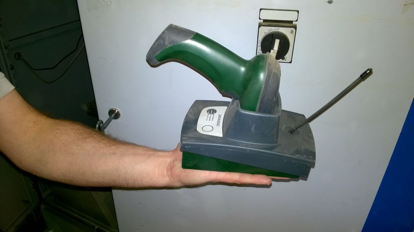
G.0004 Number : 6303 1 x left
BARCODE READER HAND SCANNER, CORDLESS
Reader: Datalogic DLL6010-R, internal decoder
no display
For reading of barcode information from
a label.
G.0007 Number : 6310 1 x left
BARCODE SOFTWARE (BARCODE CONTROL)
The barcode control is prepared for connection
to a barcode reader of Datalogic.
Software to read a barcode via the seria
interface. The software allows for the
following individual adaption of the barcode
information:
- program name
- place number
- modus for two places at the same time,
e.g. for alternating processing
left hand part
The barcode can additionally include up to
4 variables (5-digit, in 1/10 mm). When using
variables the new NC-program is automatically
generated after scanning through the production
list.
Further functions:
- Creating of production lists with help of the
barcode, additionally a rated value can be
passed on in the barcode.
- Connection of the barcode software to the
project manager (software interface to
branch packages - VKNR 6070). An imported
project which includes the barcode for this
part as an index can be processed with the
barcodes irrespective of the sequence in the
production list.
- support and vacuum cup positioning can be
displayed as a graphic or optional as a
laser projection.