Used Biesse Sektor 450 K1 Beam Saw

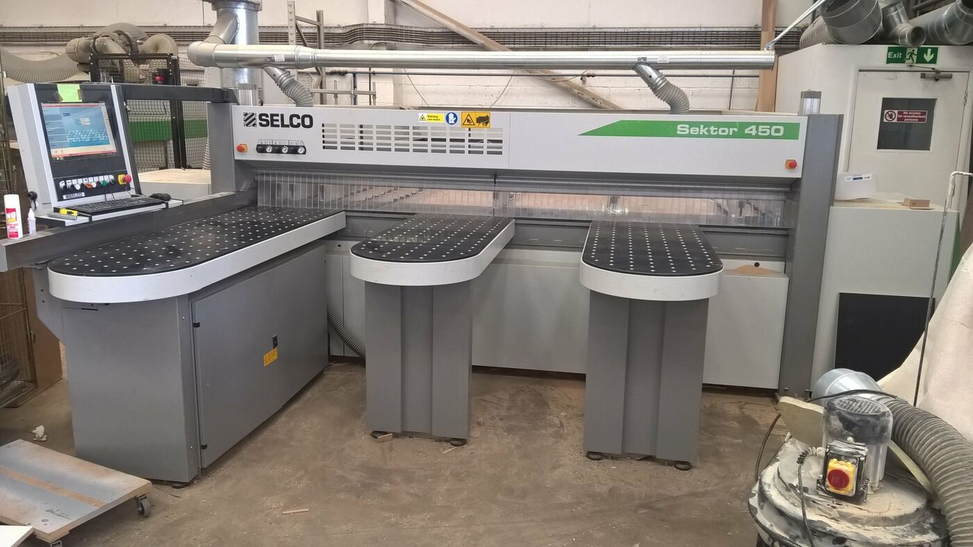
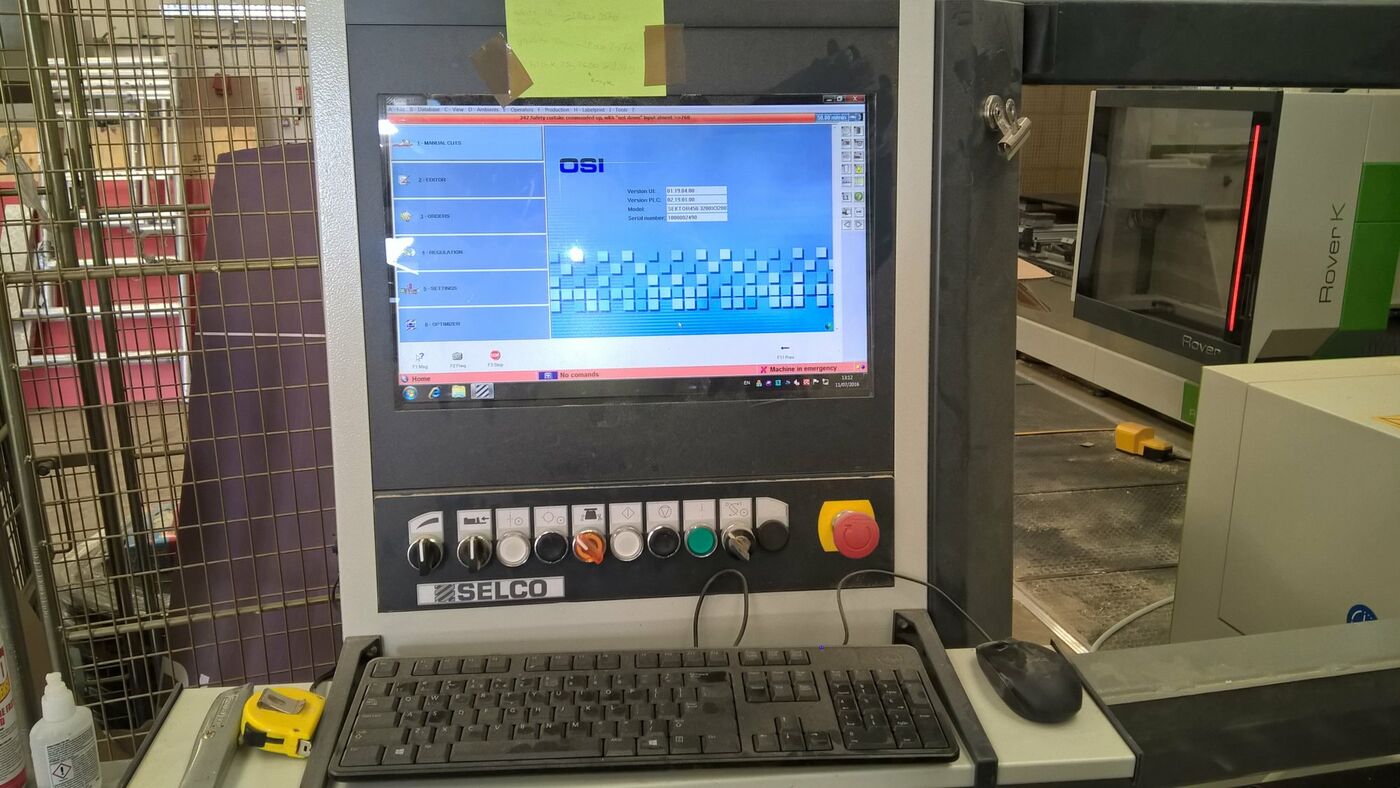
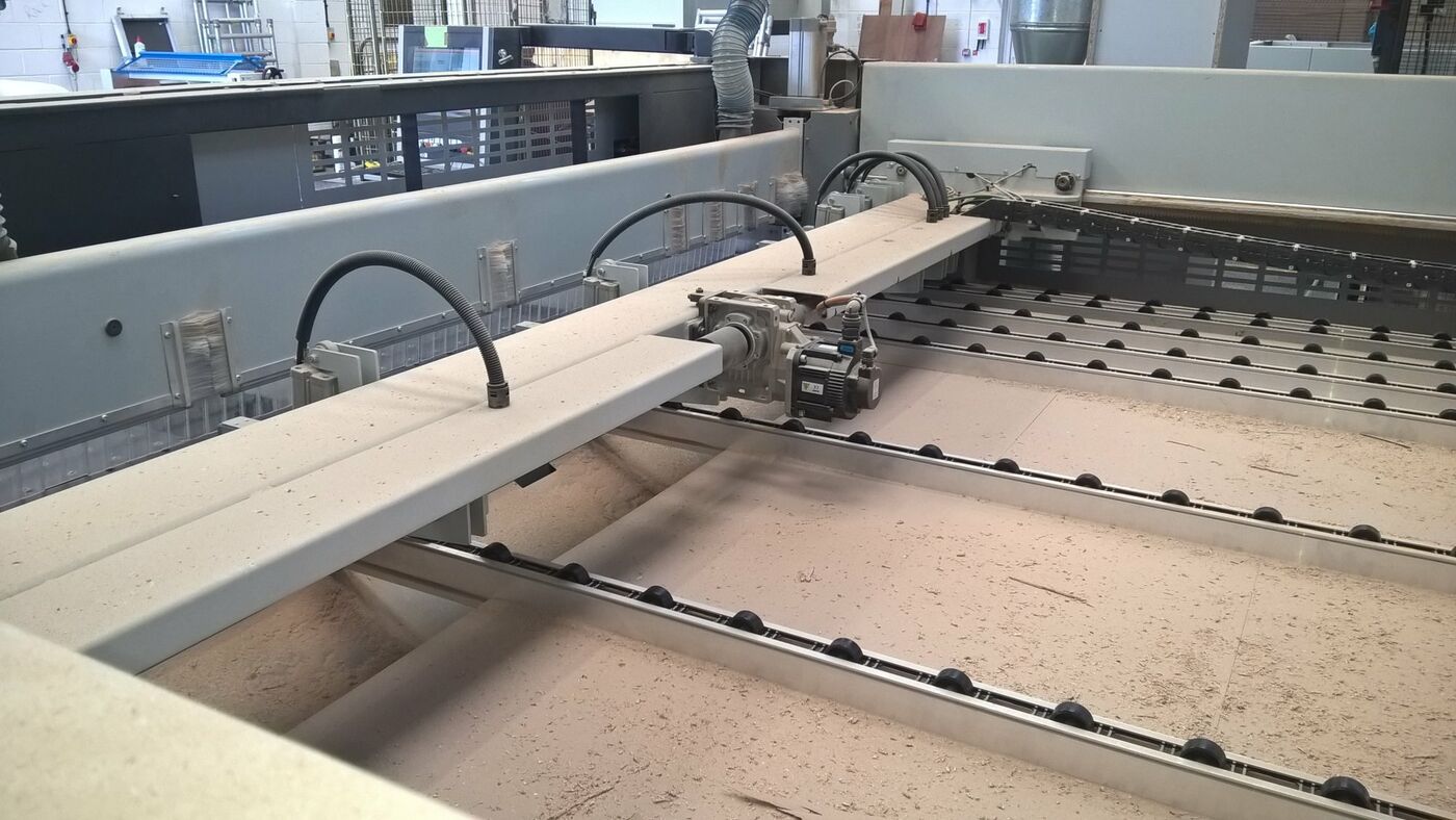
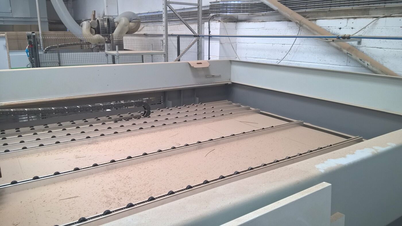
About the Used Biesse Sektor 450 K1 Beam Saw

A great opportunity to buy a nearly new Biesse Sektor 450 Beam saw.

The machine was installed in November 2014, has a cutting range of 3200 x 3200mm, has rounded air cushioned off loading tables 1500mm x 620mm and Quick OPTI software for optimising cutting patterns at the machine.

The machine has been fully serviced according to manufactures guidelines.

For more information or to view please contact our sales team on 01455 840224.

Used Biesse Sektor 450 K1 Beam Saw Features

Tick bullet point Main Base - The machine base comprises two elements, main base and secondary base, which are connected together by two side uprights. This bridge structure is capable of counteracting the forces exerted by the pressure beam and the weight of the material to cut. The main base also acts as the support for the saw carriage, which moves on two self centring prismatic wheels along a hardened round guideway located near to the saw. To further guarantee perfect contact with the guideways, each prismatic wheel is combined with an opposed counterpressure wheel. The result is that any vibrations that could adversely affect the quality of the cut are eliminated. The entire structure is balanced by two pairs of flat wheels that combine with the calibrated translation rack.
Tick bullet point Saw Carriage Structure - the saw carriage structure is made from a single piece of aluminium casting, which supports and guides the main saw blade and the scoring saw. Pneumatic raising and lowering of each saw carriage is guided by two round bars, fixed to the slides themselves, and by four ball blocks; this eliminates any vibration in the tools and guarantees improved cutting quality.The scoring saw can be adjusted horizontally, so that it is perfectly centred with respect to the main saw blade, and vertically. Adjustment is carried out from above the protection side casing, using a special wrench, even with the saw blades in motion. In this way it is possible to restrict setup times, while at the same time guaranteeing maximum safety for the operator. The extremely fast and safe saw blade replacement is obtained by means of the 'Quick Change' Selco system covered by an international patent. The saw carriage is driven by an A.C Brushless servomotor with digital technology for a perfect positioning (transmission by rack and pinion), always under direct monitoring of the numeric control. In this way it is possible to reduce the number of strokes and optimise machining times. Movement is transmitted by a helical-toothed rack and pinion system that grants precise movements and it avoids any maintenance. Adjustment of the saw carriage speed of advance is managed automatically by the numeric control, and manually from the control panel by means of the command provided. In alternative the operator can reduce it from the control panel using the manual override.By means of a specific device it is possible to execute grooves on the panel with the main saw blade. Manual adjustment from outside the machine using a special wrench, even with the blades running. In case of multiple grooves, is possible to enable the execution of the groove also during the return stroke of the saw carriage, reducing the processing time significantly. the maximum grooves depth is 45mm using the 320mm diameter main saw blade.
Tick bullet point Slide Squaring Device - Side alignment is carried out by an aligner which intervenes on the cut line and pushes the material against the square fence. Being integrated in the saw carriage structure, the positioning is extremely fast and precise, the pushing force is infinitely adjustable on the control board and, with OSI Plus option, it can be related to the different materials to be sized. With this system it is possible to perfectly align even very thin and/or flexible panels reducing cycle time.
Tick bullet point Pressure Beam - The pressure beam, which is driven by two pneumatic cylinders, guarantees strong and uniform clamping of the panels throughout the cutting cycle, including final edge trimming operations. The hold down pressure of the pressure beam is manually adjustable from the front panel. To guarantee that the pressure beam remains parallel to the work table, and therefore to ensure even clamping even in the case of small panels, a rack and pinion drive is provided. To adapt the action of the pressure bar both to long pieces (e.g during rip cutting of panels) and short ones (e.g during cross cutting of bars), two different working pressures have been foreseen on the machine, each of which can be adjusted using easily accessible devices. The part of the pressure bar in contact with the surface of the panels is covered with a rubber coating, to avoid damage to the material and. at the same time, to adapt to any undulation in the surface itself. The front part of the pressure bar is fitted with an independent sector safety barrier, made of transparent material (flap), so as to allow the operator to view the inside of the machine while restricting access to the cutting line. The rotary movement of the flap allows the cut material to be ejected, but prevents the machine operator from having to insert his hands onto the cutting line. As a further safety device, an emergency barrier is also fitted on the presser, stopping the machining cycle when triggered.
Tick bullet point Pusher Carriage - The heavy duty pusher carriage for the positioning of panels runs along heavily dimensioned steel guides. The pusher carriage is driven by a brushless motor positioned at the centre of the carriage itself. The drive is transmitted by two pinions meshing with racks that are likewise located on the guide beams, ensuring that the carriage always moves perfectly at right angles to the cutting line. In CE countries, the pusher carriage speed of advance is restricted to 25 m/min by law. Positioning of the pusher carriage is always under direct monitoring of the machine control, which uses an optical encoder mounted on a double spring loaded pinion which works directly on the rack to detect the position. This device avoids any kind of mechanical play and is insensitive to dust, humidity and magnetic fields. The pusher is fitted with independent floating grippers, to avoid any pressure between the bottom surface of the stack and the supporting table of the machine. The upper locking arm is covered with a layer of vulcanised rubber to prevent marking the top surface of the panel stack. The surface of the grippers in contact with the panels comprises aluminium stops which can be trimmed during testing to guarantee perfect alignment with the cutting line.The grippers clamping force is manually adjustable from the front panel.
Tick bullet point Supporting Stations - The table sliding the material under the pusher carriage comprises independent idle rollers, housed inside extruded aluminium elements, to avoid any friction with delicate surfaces of panels. The table of the machine base is covered with machined and calibrated H.P.L (high pressure laminate) for easy sliding of material. The front section of the machine is equipped with a rounded air table coated with scratchproof material to prevent the sectioned material from being damaged. Additional tables are available as optionals, and the configuration will be defined each time according to working requirements.
Tick bullet point PC Numeric Control - The basic version of the machine includes a PC with the following features: * 19" analogue flat panel colour monitor (wide) * Alphanumeric keyboard * Mouse * DVD Rom * Ethernet PCI Card * Intel microprocessor * Windows operating system in one of the following languages: Italian/English/French/German/Spanish. The use of a commercial PC to control the machine gives: maximum flexibility of use, simultaneous run of multiple functions, the ability to use different application software (optimiser, etc) integration with the company software network, etc. The main functions of the controls: CUTTING PATTERNS: The control is capable of managing complex cutting patterns (comprising longitudinal cuts, transversal cuts, pre cuts, single or multiple cuts of levels three and four) with graphic simulation of all operations. LISTS: By running a list it is possible to machine all the cutting patterns in that list in cascade. MANUAL CUTS: Using the manual cuts page it is possible to set a series of cutting operations on the numeric control with ease, and send them for immediate running. SIMULATION: During machining of the cutting patterns it is possible to display real time 2D graphic simulation of the panel sizing phases, indicating the sizes of cuts. DIAGNOSTICS: In the event of a problem of any kind within the machine, or of inappropriate use of the various numeric control pages, a message is displayed on the monitor indicating the cause of the problem. ONLINE HELP: It is possible to access the help page from any other page on the control. Basically speaking, the whole of the numeric control operating manual can befound on the various pages of the numeric control software itself. MAINTENANCE: For the main parts of the machine, the optimum number of hours between one maintenance operation and the next is indicated. A warning message is displayed each time a maintenance operation is required. STATISTICS: Every type of event is recorded (date and time). It is possible to process the recorded data, so as to obtain various types of information. UNITS OF MEASUREMENT: It is possible to work both in millimetres and in decimal inches. PARAMETERS: By adjusting the machine parameters it is possible to customise functions with respect to the standard configuration, so as to meet the needs of the client. The following are examples of some of these parameters: * Table of saw blade carriage speeds according to the stack size and amount of trim * Machining of cutting patterns according to the number and position of grippers * Automatic management of trim * Pick up position for the adjustable pusher.

Used Biesse Sektor 450 K1 Beam Saw Specification

Maximum length of cut 3200 mm
Maximum pusher stroke 3200 mm
Maximum saw blade projection 75 mm
Maximum gripper opening 65 mm
Height of work table 985 mm
Minimum working pressure 6 bar
Average air consumption for basic cycle 130 NI/min
Minimum pipe diameter Ø 12 (1/2")
Main saw motor power 7.5 Kw / 50 Hz (10hp) - 9 Kw / 60 Hz (12hp)
Scoring saw motor 2.2 Kw / 50 Hz (3hp) - 2.6 Kw / 60 Hz (3.6hp)
Pusher axis with brushless motor Max speed 60 m/min
Brushless motor driving saw blade carriage Speed 1 - 120 m/min
1 suction hood on the squaring side upright 100 mm
2 suction hoods on the pressure beam 100 mm
1 suction hood on the saw blade carriage 150 mm
Necessary min. air speed at suction hoods 30 m/sec
Necessary air flow 4450 m3/h