


Select and purchase Altendorf spares parts from R&J Machinery. We are the home of Altendorf UK, and offer the widest range at the best prices.
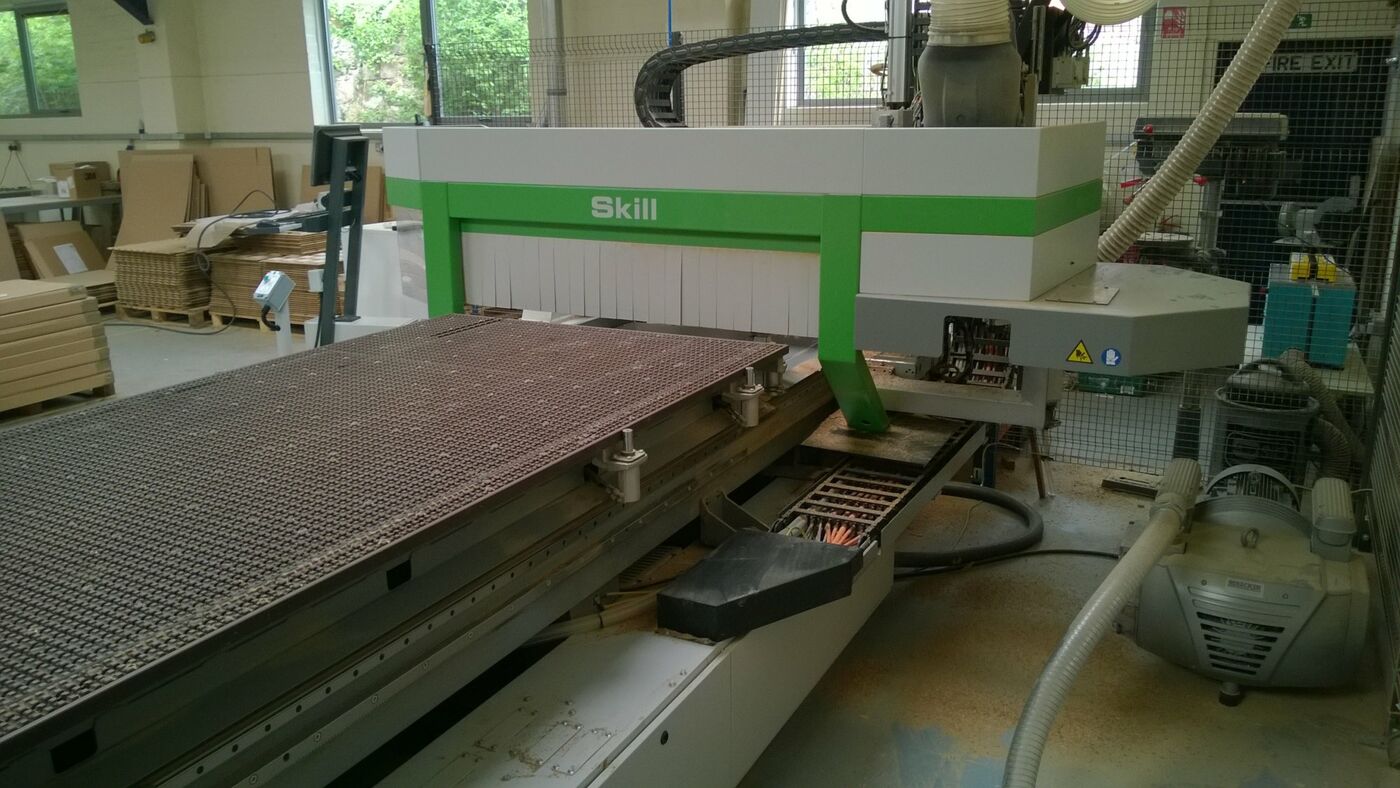
Used Biesse Skil GFT 1224
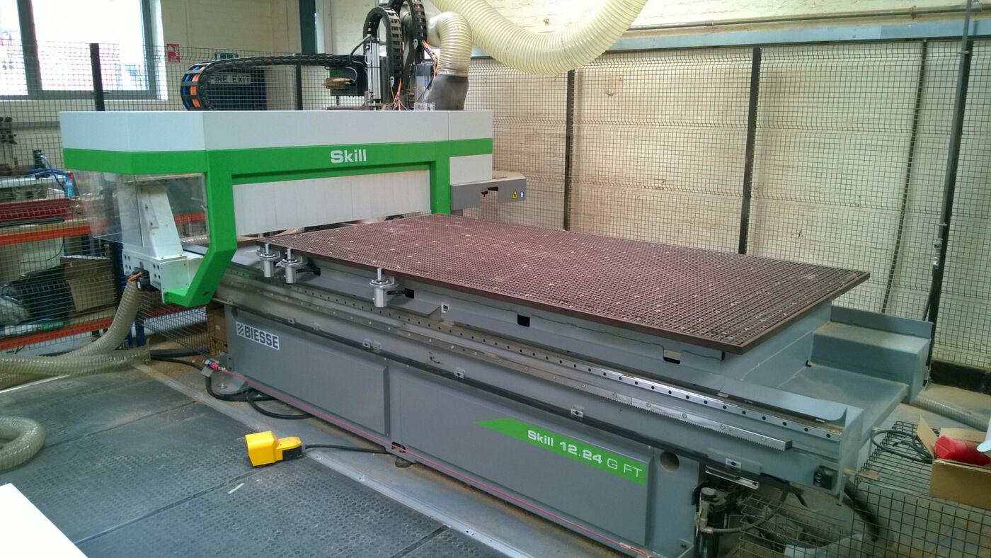
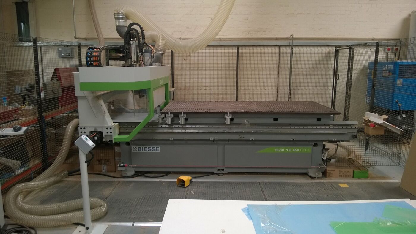
About this used Biesse Skil GFT 1224
Excellent chase to buy a Biesse Flat bed CNC for nesting and horizontal work, new 2013.
Machine available with balance of 5 year warranty, servicing and Total care cover.
Biesse Works Software
1200mm x 2400mm flat bed (Matrix)
Tool changer
Full specification available on request.
Numerically controlled machining centre SKILL 1224 G FT (4’x8)
Working fields:
X = 2465 mm; Y = 1285 mm; max. workpiece clearance in Z = 170 mm (120 mm with Sweeping Arm not including spoil panel)
Axes strokes:
X = 3321 mm; Y = 1714,5 mm; Z = 324 mm
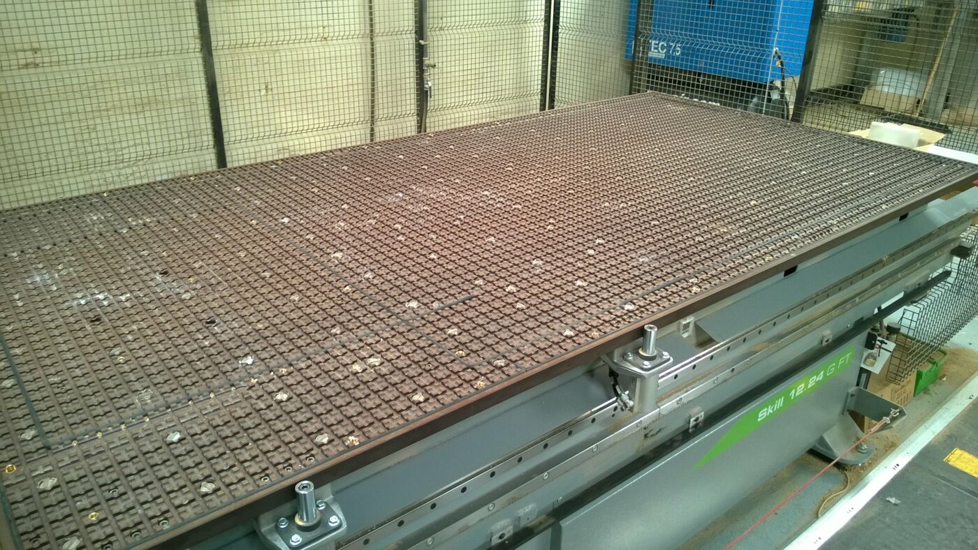
FT worktable dimensions: X = 2465 mm; Y = 1260 mm
Single area FT worktable
Manual lubrication system
2 back stops equipped with pneumatic system + 1 left side stop
3 front stops + 1 left side stop
Vacuum system for up to two 250 m3/h or 300 m3/h vacuum pumps
Electrospindle 12 kw ISO 30
Flange for the assembly of aggregates on the electrospindle
Prearrangement for the assembly of a 360° operating unit (C Axis)
4 outlets air blowing unit
Revolving tool changer with 12 places
NON EC safety devices including 1 safety mat and low fence.
BiesseWorks Basic Machine.
Biessenest Module
Numerically controlled machining centre SKILL G FT
The SKILL G FT working centres are expressly designed for the machining of elements with different shapes and dimensions in Nesting mode and the processing of general wooden elements.
As guarantee of the quality of its products and services, BIESSE has been certified ISO 9001 since 1995 and works in accordance with the UNI EN ISO 9001:2000 norms. Most of the technological components assembled on the machining centre is produced by companies of the Biesse Group or by world-wide known companies included in the Biesse "Register of Qualified Suppliers", which have strictly cooperated with Biesse through the years.
The running tests of each machining centre include the following stages:
• Intermediate control of operating units and pre-assembled components;
• Non-stop running test for the simulation of workings, for a minimum period of 10 hours;
• Control of X and Y axes precision and positioning repeatability by means of an interferometric laser (VDI/3441 norm);
• Gauging of the X and Y axes through a software function: the values detected during the laser tests are elaborated by the N.C. and transmitted to the axes drives in order to improve the positioning precision;
• Functional tests for routing and boring operations on panels positioned on all the machine origins.
Structure
All the machine structural components have been designed with a CAD product for solid modelling which allows determining the possible structural distortions caused by static and dynamic loads. The correct dimensions of the most critical components are elaborated by a software for finite elements structural calculation which, by simulating the work conditions, allows to determine the most stressed areas which need strengthening.
This definition of the machine structure grants maximum rigidity, high precision in time and refined finish to machining centres, even during heavy-duty phases.
The machine base consists of a single component made up of thick electrowelded steel sheets, suitably strengthened in the most stressed areas.
The upright, mobile in the longitudinal direction (X axis) consists of a single electrowelded steel structural work: thick steel sheets and strengthening transversal elements allow to reduce to the minimum the distortions produced by the use of the machining centre. The mobile upright is stabilized before being machined, in order to release the tension accumulated during the welding phase. High precision is granted by the fact that the upright is machined with a single positioning on the machine tool.
The transversal carriage (Y axis) and the vertical carriage (Z axis) consist of a casting in aluminium light alloy, they are stabilized and then machined on the machine tool with a single positioning.
Movement of controlled axes
The mobile upright moves along the longitudinal axis (X & Y axis) by pinion and rack, a solution that BIESSE has used for twenty years which grants acceleration parameters and movement speeds greater than those obtained through a ball screw: working times are cut down, in particular for boring operations. BIESSE uses a tempered and ground rack with helical teeth and a precision reducer with single pinion. The preloaded pinion grants smooth movement and maximum positioning precision.
Both rack and pinions are in accuracy class nr. 6 (DIN 3962 norm).
The operating unit moves in the vertical direction (Z axis), with a relatively limited travel, by means of ball screw and preloaded nut for backlash compensation and repeatability in positioning precision. The motorization is transmitted to the screw by means of a mechanic joint.
1) The ball screws are in accuracy class ISO 5.
Motorization of controlled axes
BIESSE uses Brushless motors, controlled by digital drives.
DIGITAL interface between numerical control and axes drives.
The digital system Mechatrolink grants:
• greater machining speed, since the toolpath is partly controlled by the drive instead of the numerical control;
• high working precision, thanks to faster data processing;
• high reliability, thanks to a reduced wiring system which eliminates electrical interferences typical of analogical systems;
• reduced machine stops and downtime, thanks to the error diagnostics with explanatory messages displayed directly on the N.C
Guides of controlled axes
All axes movements take place on sliding blocks coupled with linear guides which are made of tempered and ground steel. Each sliding block features 4 sliding gaskets to protect the pads guides from chips and dust. The size and the great centerdistance between the guides grant precision and optimum finish performed by the operating units.
Centralized lubrication system
For an easier maintenance, the machine is equipped with a centralized lubrication system with 2 greasing points. At each time interval set in the numerical control, a message automatically pops up on the screen, signalling the need for lubrication. The operator can use the pump the machine is equipped with to convey manually the lubricant to 2 distributors, which send the liquid to:
• sliding blocks of the linear guides of the X, Y and Z axes
• rack and pinions for X and Y axes transmission
• ball screw nuts for Z axis transmission
• sliding blocks of the linear guide for the electrospindle vertical movement, or ball screw nut if the setting axis is present
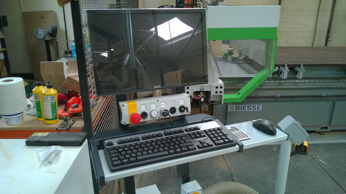
Controls on remote keyboard
Remote keyboard with potentiometer for the manual control of the axes speed, with emergency push-button and control for the tool unlocking during tooling operations.
FT Work Table
The work table is in stratified phenolic, it includes a vacuum clamping system for the pieces and has a 30 mm pitch grid for the rapid placement of the vacuum modules. The entire work table is covered with vacuum channels (D = 10 mm) with 150 mm centerdistance, and is equipped with patented plugs for a quick removal. It can be configured based on need (pitch 30 mm) with M8 threaded inserts for jig installation or other clamping equipment.
Vacuum system
One air chamber grants a constant and high level of vacuum during initial locking operations.
Vacuum system for max. no. two 250 or 300 m3/h vacuum pumps
The system supplies the vacuum to the modules for piece locking.
It includes:
• electric prearrangement for the connection of 3 vacuum pumps;
• pipes for vacuum feeding;
• digital vacuum gauge and vacuum switch connected to the emergency line.
The digital vacuum gauge grant the differentiation of the minimum vacuum safety levels during the flattening of the spoil board or the machining of pieces. Vacuum pumps are not included.
12 kW (16.1 HP) Electrospindle with ISO 30 adaptor, air cooled
Main specifications:
• 7.5 kW (10.2 HP)/7,000 rpm in S1 duty
• 10 kW (13.6 HP) from 12,000 to 16,000 rpm in S1 duty
• 12 kW (16.1 HP) from 12,000 to 16,000 rpm in S6 duty
• ceramic bearings
• Rh and Lh rotation
• rotation speed from 1,000 to 24,000 rpm, programmable by N.C
• the movement of the Z axis takes place on sliding blocks coupled with linear guides which are made of tempered and ground steel.
It includes a dust extraction hood with 5 working positions in Z controlled by the NC, in relation to the length of the tools or the different programs. The hood is automatically deactivated when the electrospindle is not working.
Flange for the assembly of aggregates on an electrospindle
The flange to be installed on the electrospindle is equipped with 4 conical seats for aggregate reference each 90°.
It can be replaced with the 360° operating unit (C axis).
Prearrangement for the assembly of a 360° operating unit (C axis)
It includes all the wiring for the electric cabinet.
It allows to reduce machine downtime for the installation of this unit on an already delivered machine
Air blower with 4 exits.
It blows simultaneously in the 4 directions X+, X-, Y+, Y- to help the extraction of chips and dust, and is particularly useful during nested-based machining.
Installed on the dust extraction hood, it blows very close to the panel, for maximum efficiency.
Prearrangement for the assembly of auto-floating aggregates.
Numerical Control
PC-based control system BH660.
Thanks to the new Biesse technology WRT (Windows Real Time), which increases the performances of Windows XP by making it work in real time, the machine is controlled directly by the PC, and any other hardware component becomes unnecessary.
Since the software that controls the machine runs directly on a personal computer and not on a dedicated hardware device, the system architecture is greatly simplified, grants greater performance and reliability.
BiesseWorks machine version
Graphic operator interface BiesseWorks machine version.
The graphic interface, fully compatible with the Windows standard, grants the following functions:
• Assisted graphic editor for the programming of boring, cutting and routing operations. The Editor handles multiple documents, so it is easy to copy a machining operation from one document to another through the Windows copy/paste functions;
• Interactive graphic views with zoom function. It is possible to select machining operations graphically and modify their technological parameters;
• Automatic optimization of borings, tool changes and tool routes;
• Possibility of defining the work sequence with the mouse, by selecting the workings from a list;
• Parametric programming, with the possibility of specifying the values of the parameters when a parametric program is run;
• Import of files from CAD and other outside software systems in DXF,CID3 and CIX format. DXF files can be purely geometric or can contain all the technological parameters necessary for machining;
• Conversion of groups of DXF,CID3 and CIX files with no need of importing them one by one (batch-run module);
• Possibility of executing DXF,CID3 and CIX files directly;
• Guided creation of customized parametric macros, with the possibility of recalling them through icons which can be included in the software interface;
• Graphic configuration of machine data;
• Tool database with search filters helping tool selection. It is possible to associate a shaped profile in DXF to every tool and automatically generate its 3D representation;
• Mouse selection for operating units and tool changers tooling operations;.
BiesseNest Module
Entry-level software module for nested-based manufacturing.
* It requires the software 'BiesseWorks'
This module allows operators to create a project for the automatic positioning of the pieces to be produced on rough material sheets, so as to minimize material waste and optimize the respective work programs. The module produces a series of BiesseWorks programs (BPP).
A BiesseNest project allows the import of:
• BiesseWorks (BPP) programs, even parametric, with the possibility of modifying the values of the parameters
• CID3 and CIX files
• DXF drawings
With BiesseNest panels can have any type of shape. The workings are arranged so as to minimize tool change and machine movement, and to perform through workings last.
BiesseNest can print labels and drawings:
• the label for each produced piece following the machining order, sheet by sheet
• the drawing of the cutting list for each rough material sheet with identification methods helping users stick the labels on the right pieces
The project can be defined manually within BiesseNest or it can be imported, in the following formats:
• formatted text file created by an external file or exported from an Excel worksheet
• XML file
Desktop Personal Computer
Main technical specifications:
• CPU Intel(R) DualCore > 2.2GHz
• 2 GB RAM memory
• 160 GB hard disk or superior
• 19" LCD
• keyboard
• mouse
• DVD reader
• serial port RS-232
• USB ports
• Ethernet card for network connection to an office PC
These technical specifications may be subject to updates
Since the personal computer controls the processes BIESSE does not allow the installation of additional non-authorized software, under penalty of losing the guarantee.
Statistics
Machine statistics, capable of collecting general information on machine events in order to record reliability over time.
Teleservice
It allows an immediate and direct access to the machine numerical control. This way it is possible to check machine data, user programs, input/output signals and system variables, and to install software updates, therefore granting:
• real-time answers
• quick problem solving
• strong reduction of machine downtime
• real-time software updates
The teleservice support is free of charge for the whole warranty period.
ELECTRIC SYSTEM
The machine is equipped with some controlling devices (e.g. electrovalves, input/output modules, …) which are assembled next to the items they control, and are provided with the electronic circuits necessary for their interface with the field bus: this greatly simplifies the electric system, with obvious advantages as far as diagnostics and maintenance.
Electric cabinet
The machine can be powered at 380/400/415 V - 50/60 Hz.
The electric cabinet and the inner components comply with the CEI EN 60204-1 and CEI EN 60439-1 norms.
The auxiliary transformer supplies the connection voltage for the personal computer, the air conditioner and the electrospindles cooling fans, avoiding the use of the middle neutral wire, not always available.
The electronic equipment is powered by a stabilized 24 V DC power supplier.
Air conditioner for electric cabinet
It allows:
• the perfect working of all the electronic components included in the electric cabinet, even at very high temperatures, up to 40°C (104°F);
• a dust-free environment, since there are no aeration fans.
Inverter for electrospindles with power up to 12 kW
Static frequency converter. The equipment includes:
• frequency visualized on the display;
• tool rotation speed visualized on the display;
• display for diagnostics messages;
• reset push-button;
• automatic control for decelerating the tool rotation;
• resistor for the dissipation of braking power;
• n.c. programming of the tool rotation speed.
NON CE safety devices with low fencing
It includes:
• front safety mat equipped with control unit providing internal safety;
• software X axis movement control to protect the operator
• emergency rope placed in front of the machine;
• operating unit cover made of structural and protective plates, 20 layers of overlapping strips (for a total thickness of 15 mm), and a transparent panel in crushproof polycarbonate allowing operators to work in total safety since it grants maximum visibility;
• emergency button positioned on the N.C.;
• emergency button positioned on the PC console.
• the remote control panel includes commands to operate the machine fulfilling security requirements (emergency button, tool unlocking and feed speed adjustment ...).
• Security fence: height 1.2 m
Emergency recovery procedure
This function allows operators to restart an interrupted working due to a machine emergency stop. The program restarts exactly from where it was interrupted, by following a specific procedure. The working can be restarted when the emergency stop happened during:
• a work cycle with the electrospindle;
• a boring cycle;
• a cutting cycle;
• an automatic tool change on a revolving or chain tool changer;
• any movement controlled by ISO lines.
The introduction of this function avoids throwing away half-finished pieces, which sometimes are valuable materials (rare woods, etc.). It also allows operators to save time in case of long programs.
Manuals
• Installation instructions
• User's manual
• Software instructions
• Pneumatic and wiring diagrams
• CD InDocs containing the spare parts catalogue
• Machine installation form
Maintenance equipment
• Device for locking and unlocking tools from tool-holders;
• set of wrenches;
• greasing pump;
• grease for the lubrication of ball bushings;
• grease for the lubrication of boring head and aggregates.
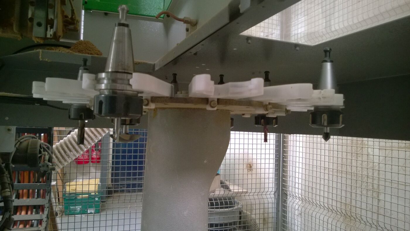
REVOLVING TOOL CHANGER WITH 12 PLACES
Installed on the Y carriage, it allows having up to 12 tools and aggregates always available granting high productivity.
Main specifications:
• tool grippers centerdistance: 114 mm;
• tools which can be stored: 12 tools with a diameter of 110 mm;
• aggregates: check tool-changer layout;
• max. tool diameter: 160 mm in alternate mode;
• max. tool length: 273 mm - check tool-changer layout;
• max. weight of tool or aggregate + tool: 7,5 kg;
• max. total weight: 45 kg.
Prearrangement for digital Presetter for the measurement of the tool length
It includes all the harness for the electric cabinet.
CE Safety devices according to Directive 2006/42/CE for base machine.
This solution complies with:
• machine Directive 2006/42/CE;
• electromagnetic compatibility Directive 89/336/EEC and later amendments;
• low voltages Directive 73/23/EEC and later amendments.
It includes:
• mechanical cam and safety microswitch to protect the operator when the cycle starts;
• Safety protection fence: height 2 m
7550008
1
Presetter for the measurement of the tool length with diameter up to 130 mm.
Digital device for tool length measurement by contact plate.
The device checks the tool length and updates the values in the tool schedule of Numerical Control.
The diameter of the contact plate is 130 mm.
We recommend the use of the blowing device for the cleaning of the reading surface.
The measurable lengths (min/max) must be verified on the specific layout.
* Includes a null cone for the device setting.
7200060
1
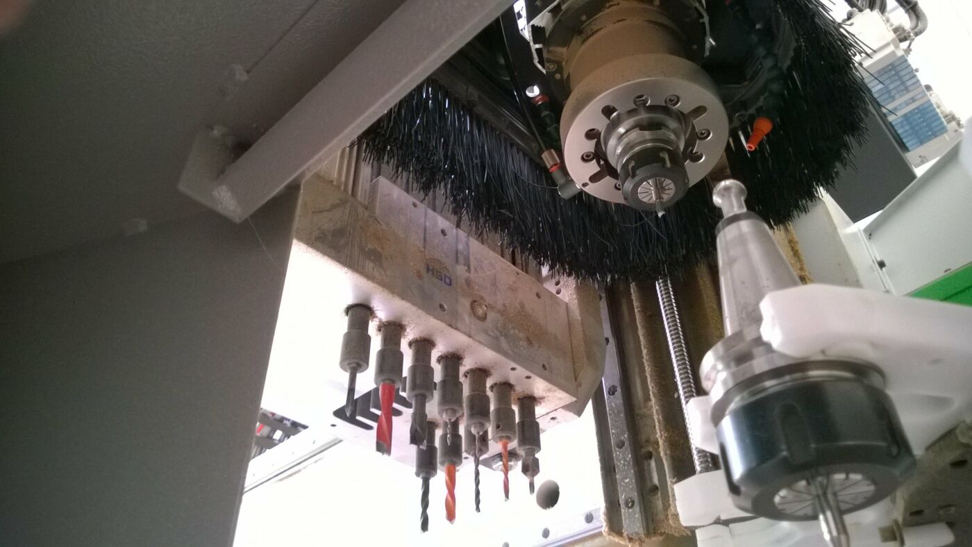
Boring head BH 10 A
Working unit which can be equipped with up to 10 independent tools for single and multiple borings on upper panel surface.
The spindles have an alternate Rh/Lh rotation and move by means of precision ground helical teeth which grant maximum operating accuracy and silence.
The head is composed of:
• 10 independent vertical spindles at a centerdistance of 32 mm, 7 of which are placed along X and 3 along Y;
The spindles are driven by 1 motor controlled by inverter (motor power 1.7 kW at 2800 rpm - 3 kW at 6000 rpm): the spindle rotation speed can be adjusted up to 6000 rpm, to perform quick boring cycles and therefore reduce the working time. In addition, it is possible to choose the rotation speed according to the tools employed and the material type.
7000201
1
Automatic lubrication system.
At each time interval, programmable through the numerical control, the pump automatically sends the lubricant to the following machine components, with no machine downtime and no operator's intervention:
• X axis: 4 sliding blocks of the linear guides and rack (in two points)
• Y axis: 4 sliding blocks of the linear guides and rack
• Z axis: 4 sliding blocks of the linear guides and ball screw nut, for each machine Z axis
• Revolving tool changers: sliding block of the linear guide, if present.
When the quantity of lubricant in the tank is below the minimum a message appears on the n.c. screen.
7530075
1
SOFTWARE UPDATE from BiesseWorks (machine version) to BiesseWorks Advanced (machine version).
BiesseWorks Advanced includes the following additional functions with respect to BiesseWorks:
• Guided creation of customized parametric macros, with the possibility of recalling them through icons which can be included in the software interface;
• 3D simulation of the tool path, to allow the operator to check on the PC the real situation on-board the machine, thus detecting of any errors in advance;
• Approximate calculation of machining time;
• Parametric programming of the work area: by changing the parameters the programs automatically adjust both the workings and the positioning of the elements on the work area;
• Automatic pocketing of any shape with the possibility of leaving islands in relief at different depths;
• Text engraving using Windows True Type Fonts;
• Possibility of defining rotated or circular faces in addition to the six standard faces available in the editor. Programming for these faces is entirely similar to programming the standard faces;
• Programming of the chip deflector aggregate.
Compatible with NC1000 rel. 2.0.0.1 or updated.
7001200
1
Complete set of tools for Rover machines running test.
It includes:
• bits: n.8 dia.8; n.4 dia.10; n.8 dia.5; n.2 for through holes dia.5; n.1 dia.35;
• tools for routing units: n.1 dia.6; n. 1 diam.18; n.2 spare knives
• n. 4 elastic collets, 2 ERC32 and 2 ERC40 dia. 10 mm and 20 mm
7530074
1
BIESSEWORKS - Advanced programming system - office version (2 hardware keys).
Compatible with the numerical controls BH660, XP 600, NC1000, Xnc, Xnc Compact rel. 2.0.0.0 and updated.
It requires the operating system Windows XP.
* For NC BH660, XP600 and NC1000 it requires BiesseWorks Advanced - machine version.
The graphic interface, fully compatible with the Windows standard, grants the following functions:
• Assisted graphic editor for the programming of boring, cutting and routing operations. The Editor handles multiple documents, so it is easy to copy a machining operation from one document to another through the Windows copy/paste functions;
• Interactive graphic views with zoom function. It is possible to select machining operations graphically and modify their technological parameters;
• Automatic optimization of borings, tool changes and tool routes;
• Possibility of defining the work sequence with the mouse, by selecting the workings from a list;
• Parametric programming, with the possibility of specifying the values of the parameters when a parametric program is run;
• Management of sub-programs: insertion of different bbp programs into a single program with optimization of sequential processes;
• Import of files from CAD and other outside software systems in DXF, CIX and CID3 format. DXF files can be purely geometric or can contain all the technological parameters necessary for machining;
• Conversion of groups of DXF, CIX and CID3 files with no need of importing them one by one (batch-run module);
• Possibility of executing DXF, CIX and CID3 files directly;
• Automatic calculation of the position of panel supports and sliding bases at the "start" of the program
• Graphic configuration of machine data;
• Tool database with search filters helping tool selection. It is possible to associate a shaped profile in DXF to every tool and automatically generate its 3D representation;
• Mouse selection for operating units and tool changers tooling operations;
• Graphic set-up of panel supports: immediate detection of tool collisions with piece locking devices, automatic generation of the set-up on symmetric or translated origins and possibility of defining the rotation of the vacuum modules.
BiesseWorks Advanced also includes:
• Guided creation of customized parametric macros, with the possibility of recalling them through icons which can be included in the software interface;
• 3D simulation of the tool path, to allow the operator to check on the PC the real situation on-board the machine, thus detecting of any errors in advance;
• Approximate calculation of machining time;
• Parametric programming of the work area: by changing the parameters the programs automatically adjust both the workings and the positioning of the elements on the work area;
• Automatic pocketing of any shape with the possibility of leaving islands in relief at different depths;
• Text engraving using Windows True Type Fonts;
• Possibility of defining rotated or circular faces in addition to the six standard faces available in the editor. Programming for these faces is entirely similar to programming the standard faces;
• Programming of the chip deflector aggregate
Min. PC requirements:
- Pentium processor 2 Ghz or equivalent
- 512 Mb RAM (1 Gb advised)
- 1 Gb of free disk space
- graphic card with at least 128 Mb of RAM advised